Note
Go to the end to download the full example code.
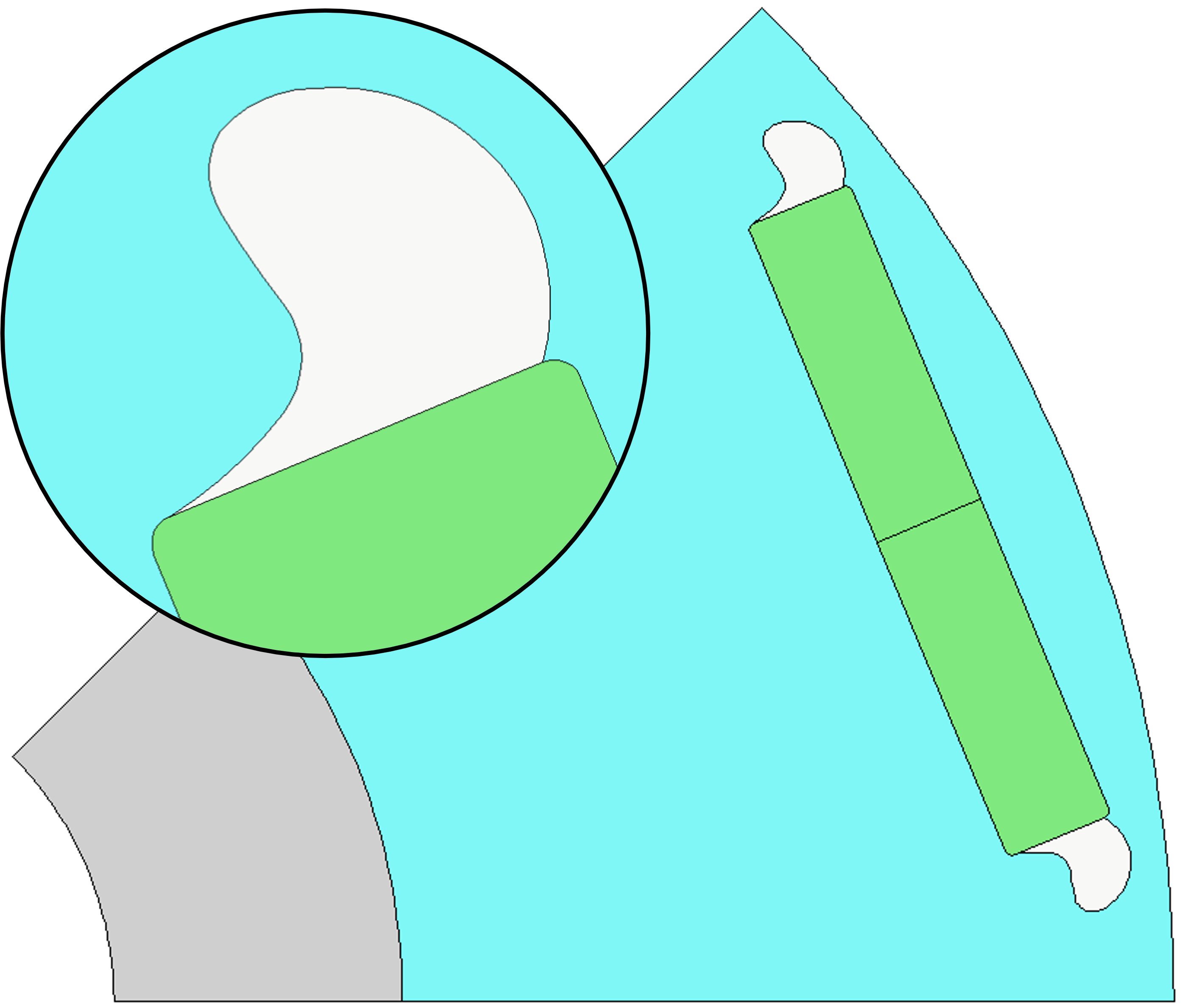
Bezier curve rotor pockets#
This script applies the adaptive templates functionality to modify rotor pockets with a custom curve defined using a Bezier function.
Note
This script requires Motor-CAD 2024 R2 or later.
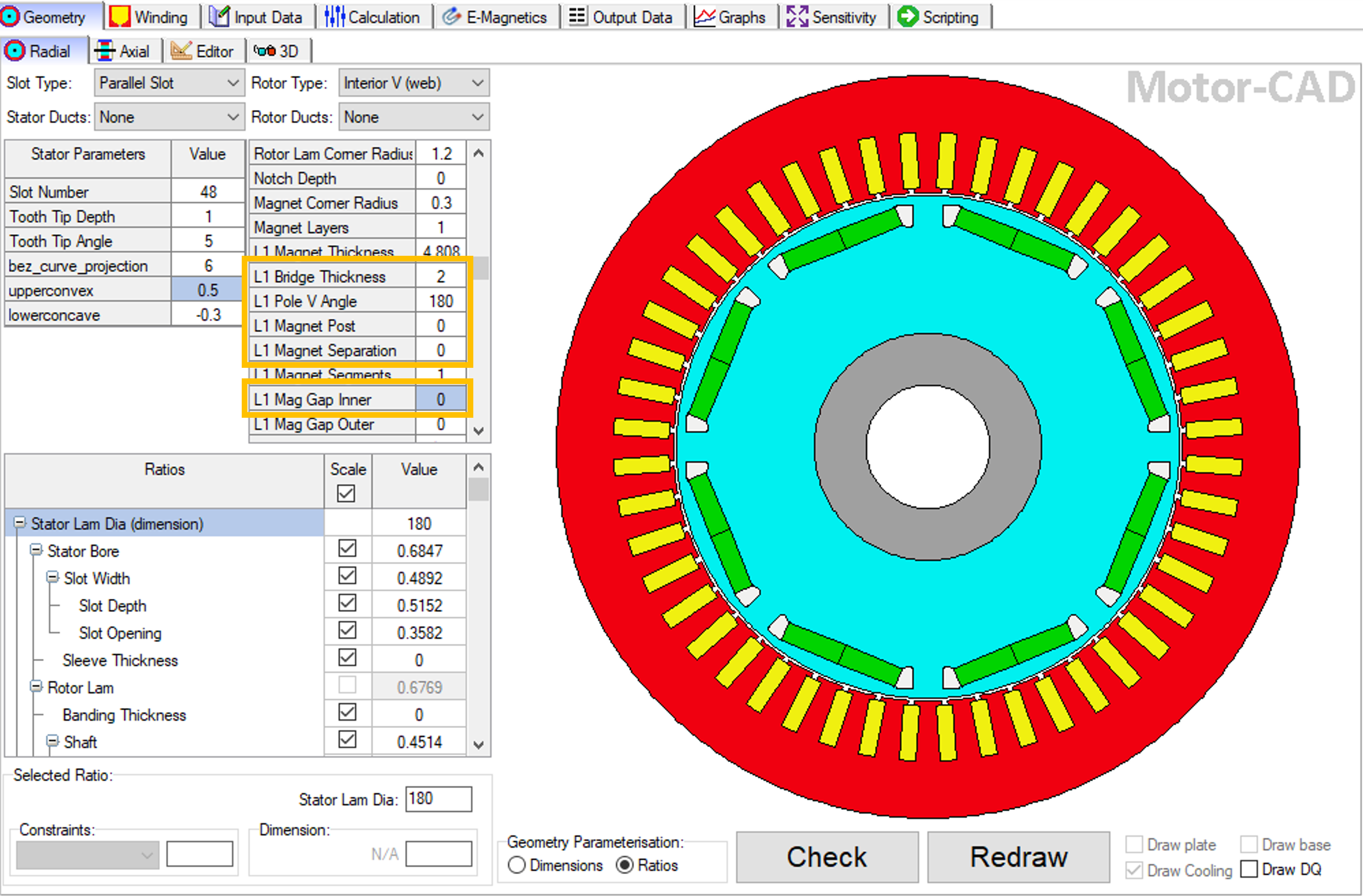
This script is designed to be run from a Motor-CAD model based on the e4a template (a 48 slot, 8 pole IPM machine). The model is modified from the template by adjusting the Standard Template geometry parameters as follows:
Set L1 Bridge thickness to 2 mm.
Set L1 Pole V Angle to 180 degrees.
Set L1 Magnet Post to 0 mm.
Set L1 Magnet Separation to 0 mm.
Set L1 Mag Gap Inner to 0 mm.
If no Motor-CAD file is open, the e4a template is loaded and the geometry is adjusted as described earlier.
Perform required imports#
Import the pymotorcad package to access Motor-CAD.
Import the Coordinate, Arc, Line and rt_to_xy objects
to define the adaptive template geometry.
Import bezier used to draw the curve.
Import the os, shutil, sys and tempfile packages
to open and save a temporary MOT file if none is open.
import os
import shutil
import sys
import tempfile

import ansys.motorcad.core as pymotorcad
from ansys.motorcad.core.geometry import Arc, Coordinate, Line, get_bezier_points, rt_to_xy
from ansys.motorcad.core.geometry_fitting import return_entity_list
Connect to Motor-CAD#
If this script is loaded into the Adaptive Templates file in Motor-CAD, the current Motor-CAD instance is used.
If the script is run externally, these actions occur: a new Motor-CAD instance is opened,
the e4a IPM motor template is loaded, the geometry changes described earlier are applied and the
file is saved to a temporary folder. To keep a new Motor-CAD instance open after executing the
script, use the MotorCAD(keep_instance_open=True) option when opening the new instance.
Alternatively, use the MotorCAD() method, which closes the Motor-CAD instance after the
script is executed.
if pymotorcad.is_running_in_internal_scripting():
    # Use existing Motor-CAD instance if possible
    mc = pymotorcad.MotorCAD(open_new_instance=False)
else:
    mc = pymotorcad.MotorCAD(keep_instance_open=True)
    # Disable popup messages
    mc.set_variable("MessageDisplayState", 2)
    if not "PYMOTORCAD_DOCS_BUILD" in os.environ:
        mc.set_visible(True)
    mc.load_template("e4a")

    # Set Standard Template geometry ready for Adaptive Templates script
    mc.set_array_variable("BridgeThickness_Array", 0, 2)  # Bridge thickness set to 0
    mc.set_array_variable("PoleVAngle_Array", 0, 180)  # Pole V angle set to 180
    mc.set_array_variable("VShapeMagnetPost_Array", 0, 0)  # Magnet Post set to 0
    mc.set_array_variable("MagnetSeparation_Array", 0, 0)  # Magnet Separation set to 0
    mc.set_array_variable("VShape_Magnet_ClearanceInner", 0, 0)  # Magnet Inner Gap set to 0

    # Open relevant file
    working_folder = os.path.join(tempfile.gettempdir(), "adaptive_library")
    try:
        shutil.rmtree(working_folder)
    except:
        pass
    os.mkdir(working_folder)
    mot_name = "IPM_Pocket_Bezier"
    mc.save_to_file(working_folder + "/" + mot_name + ".mot")

# Reset geometry to default
mc.reset_adaptive_geometry()
Set adaptive parameter if required#
The set_adaptive_parameter_default function checks if a parameter exists. If not,
it creates the parameter with a default value.
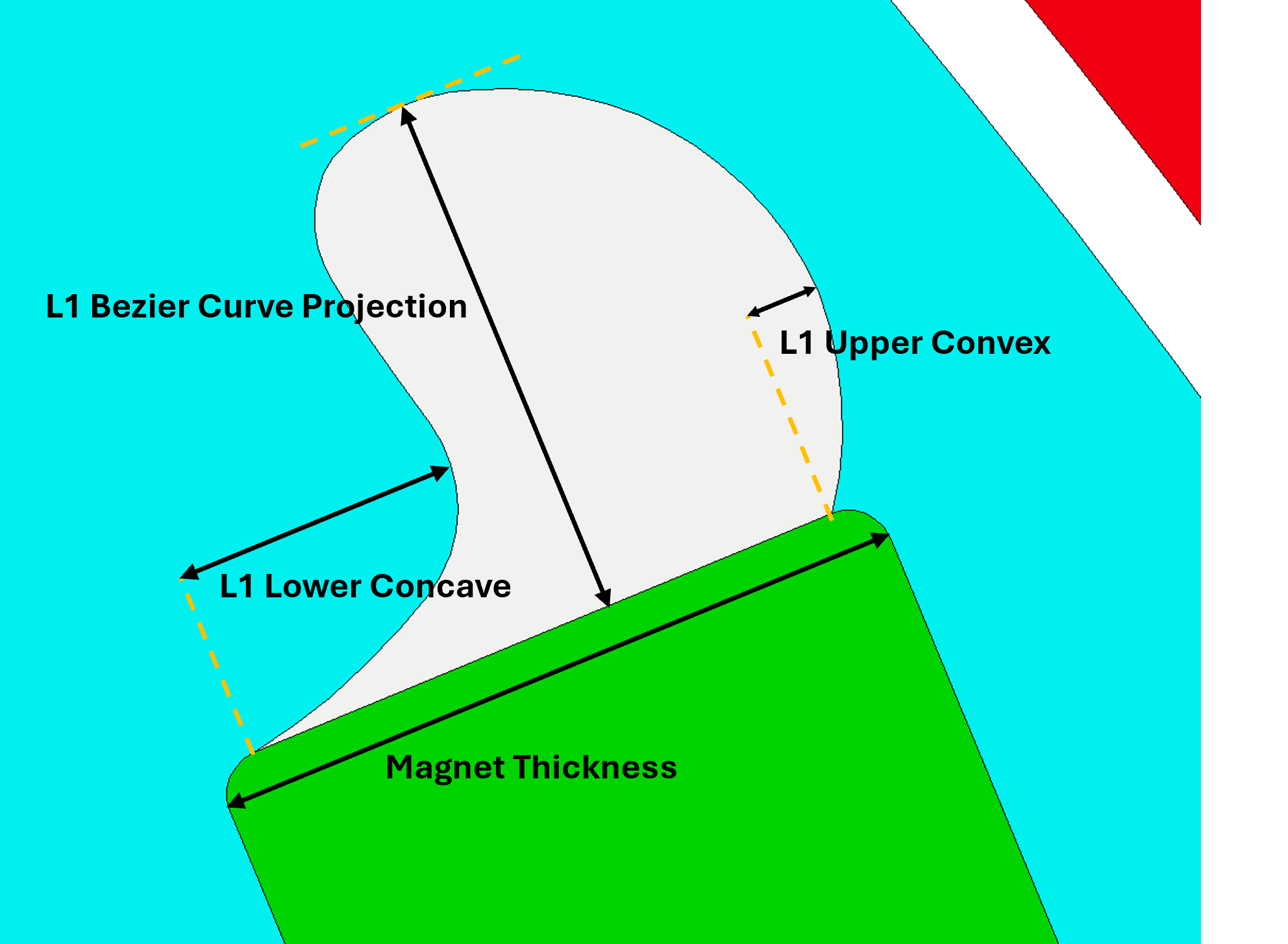
Set the required L1 Bezier Curve Projection, L1 Upper Convex and L1 Lower Concave
parameters if undefined.
mc.set_adaptive_parameter_default("L1 Bezier Curve Projection", 6)
mc.set_adaptive_parameter_default("L1 Upper Convex", 0.5)
mc.set_adaptive_parameter_default("L1 Lower Concave", -0.3)
The adaptive parameters are used to define the curved rotor pocket geometry with a Bezier function. The parameters relate to the rotor pocket shape as follows:
L1 Bezier Curve Projection: Defines the rotor pocket extension beyond the magnet edge in the direction of the magnet length in mm.L1 Upper Convex: Defines the concave rotor pocket extension beyond the magnet edge in the direction of the magnet thickness. This parameter is dependent on the magnet thickness (a Standard Template parameter).L1 Lower Concave: Defines the convex rotor pocket curvature in the direction of the magnet thickness. This parameter is dependent on the magnet thickness (a Standard Template parameter).
Get required parameters and objects#
From Motor-CAD, get the adaptive parameters and their values.
Get the standard template rotor region. This can be drawn for debugging if required.
rotor_region = mc.get_region("Rotor")
rotor_radius = mc.get_variable("RotorDiameter") / 2
poles = mc.get_variable("Pole_Number")
pole_angle = 360 / (poles * 2)
Get the adaptive parameters specified in Motor-CAD, and their values
totalprojection = mc.get_adaptive_parameter_value("L1 Bezier Curve Projection")
upperconvex = mc.get_adaptive_parameter_value("L1 Upper Convex")
lowerconcave = mc.get_adaptive_parameter_value("L1 Lower Concave")
Get the Rotor Pocket regions
Rotor_Pocket_regions = []
for i in rotor_region.child_names:
    if "Pocket" in i:
        Rotor_Pocket_regions.append(mc.get_region(i))
Get the magnet regions
Magnet_regions = []
for i in rotor_region.child_names:
    if "Magnet" in i:
        Magnet_regions.append(mc.get_region(i))
Find the magnet edge that is shared with the first rotor pocket
for j in Magnet_regions:
    for i in j.entities:
        MagnetFaceLine = Rotor_Pocket_regions[0].find_entity_from_coordinates(i.start, i.end)
        if MagnetFaceLine is not None:
            break
Get properties of the magnet edge that are to be used to define the new rotor pocket geometry
LineLength = MagnetFaceLine.length
StartCoordinate = MagnetFaceLine.start
Create the Adaptive Templates geometry#
Remove all existing entities from the first rotor pocket
Rotor_Pocket_regions[0].entities.clear()
Define the x-y points that are to be used to draw the new rotor pocket. The points are defined relative to a vertical magnet edge (parallel to the y axis).
control_points = [
    Coordinate(0.0, 0),
    Coordinate(totalprojection * -0.2, (1 - 1 * lowerconcave) * LineLength),
    Coordinate(totalprojection * -0.5, -0.5 * LineLength),
    Coordinate(-1 * totalprojection, 0.5 * LineLength),
    Coordinate(totalprojection * -0.5, (1 + upperconvex) * LineLength),
    Coordinate(0.0, 1 * LineLength),
]
Create set of points for drawing the calculated bezier curve
num_pts = 256
xylist = get_bezier_points(control_points, num_pts)
Create a list of entities from the curve points
linetolerance = 0.01
arctolerance = 0.01
bez_curve_entities = return_entity_list(xylist, linetolerance, arctolerance)
Add the new entities that make up the curve to the first rotor pocket region Counts the number of arcs and lines
Translate (move) the rotor pocket region in the x-y plane to the magnet edge
Rotor_Pocket_regions[0].translate(StartCoordinate.x, StartCoordinate.y)
Rotate the rotor pocket region to match the magnet edge
Rotor_Pocket_regions[0].rotate(StartCoordinate, -(90 - MagnetFaceLine.angle))
Add the magnet edge line to the rotor pocket region
Rotor_Pocket_regions[0].add_entity(MagnetFaceLine)
Check that the rotor pocket region is joined up and set the region in Motor-CAD
if Rotor_Pocket_regions[0].is_closed():
    mc.set_region(Rotor_Pocket_regions[0])
Mirror the first rotor pocket region on the other half of the rotor. Define the mirror line from
the origin and use the Region.mirror() method to create a new region named mirroredRegion
from the rotor pocket region.
mirrorlinex, mirrorliney = rt_to_xy(rotor_radius, pole_angle)
mirrorLine = Line(Coordinate(0, 0), Coordinate(mirrorlinex, mirrorliney))
mirroredRegion = Rotor_Pocket_regions[0].mirror(mirrorLine)
Use the Region.replace() method to replace the entities in the second rotor pocket with those
from the new mirroredRegion. The properties of the second rotor pocket (such as name,
material, colour) are retained.
Rotor_Pocket_regions[1].replace(mirroredRegion)
Check that the rotor pocket region is joined up and set the region in Motor-CAD
if Rotor_Pocket_regions[1].is_closed():
    mc.set_region(Rotor_Pocket_regions[1])
Load in Adaptive Templates script if required#
When this script is run externally, the script executes the following:
Set Geometry type to Adaptive.
Load the script into the Adaptive Templates tab.
Go to the Geometry -> Radial tab to run the Adaptive Templates script and display the new geometry.
Note
When running in a Jupyter Notebook, you must provide the path for the Adaptive Templates script
(PY file) instead of sys.argv[0] when using the load_adaptive_script() method.
if not pymotorcad.is_running_in_internal_scripting():
    mc.set_variable("GeometryTemplateType", 1)
    mc.load_adaptive_script(sys.argv[0])
    mc.display_screen("Geometry;Radial")
Total running time of the script: (0 minutes 45.222 seconds)