Motor-CAD adaptive templates scripting#
Note
Adaptive Templates in Motor-CAD require v2024.1.2 (Motor-CAD 2024 R1 Update) or later and PyMotorCAD v0.4.1. To update PyMotorCAD in Motor-CAD, go to Scripting -> Settings -> PyMotorCAD updates and select ‘Update to Latest Release’.
This guide describes the Adaptive Templates feature. Motor-CAD provides the Adaptive Templates feature for the design of models with geometries that cannot be modelled using the standard template geometries. By using the Adaptive Templates feature, users can generate their own geometric parameterisations from scratch or based on the Standard Templates.
Using Adaptive Templates, custom geometric parameterisations are set up using a Python script.
Adaptive Templates examples are available in the PyMotorCAD Documentation under Adaptive templates examples. For the examples shown in this user guide, see Triangular Rotor Notches for IPM and Curved Rotor Flux Barriers for SYNCREL U-Shape.
Those who are new to Motor-CAD Adaptive Templates should work through the tutorial supplied with Motor-CAD. The tutorial contains additional information and full workflow examples.
Geometry editor#
The Geometry -> Editor tab in Ansys Motor-CAD shows each geometry region currently in use in the model.
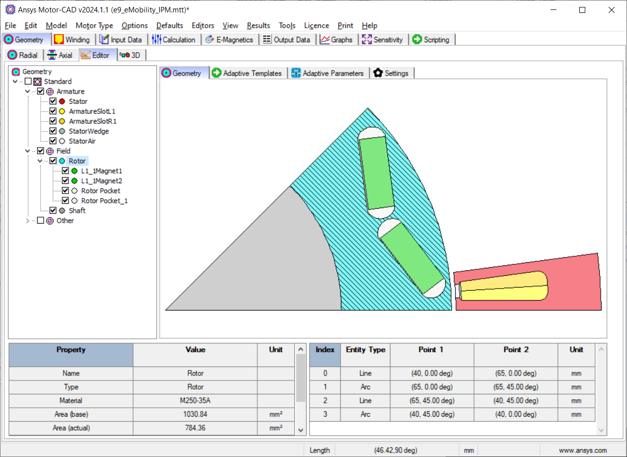
Geometry -> Editor -> Geometry tab in Ansys Motor-CAD 2024 R1#
The interface is fully interactive. Individual geometry regions can be selected from the region tree or the diagram.
Motor geometry components are grouped by Armature and Field and represented by regions. The Editor displays the geometry regions based on their spatial locations, such that a region’s sub-regions are shown as a descendant/child of their parent region.
The e9 IPM template in Motor-CAD is shown. In this example, the Magnet and Rotor Pocket regions (L1_1Magnet1, L2_1Magnet2, Rotor Pocket and Rotor Pocket_1) are shown in a branch underneath the Rotor region. When a region is selected, region properties are displayed at the bottom-left of the screen and region entities at the bottom-right.
Region properties include the Name, Type, Material, Area (base and actual), Position (Centroid, Region Coordinate) and Symmetry of the region. Region entities include all the Lines and Arcs that define the region. The Rotor region in the e9 IPM template is defined by two lines and two arcs. If an individual entity is selected from the table, it is highlighted in the diagram.
Either Cartesian or Polar coordinate systems can be used. The coordinate system can be changed by going to Input Data -> Settings -> Geometry.
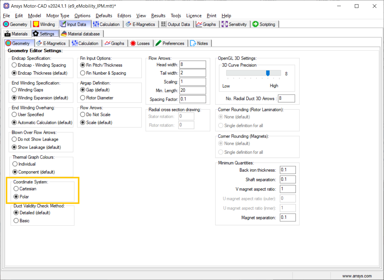
Input Data -> Settings -> Geometry tab in Ansys Motor-CAD 2024 R1#
Adaptive templates script#
Adaptive Templates can be enabled by going to the Geometry -> Editor -> Adaptive Templates tab and setting the Geometry Templates Type from Standard to Adaptive. This means that the Adaptive Templates script is run every time the Motor-CAD geometry is created, and the scripting interface enabled, which allows editing of the script.
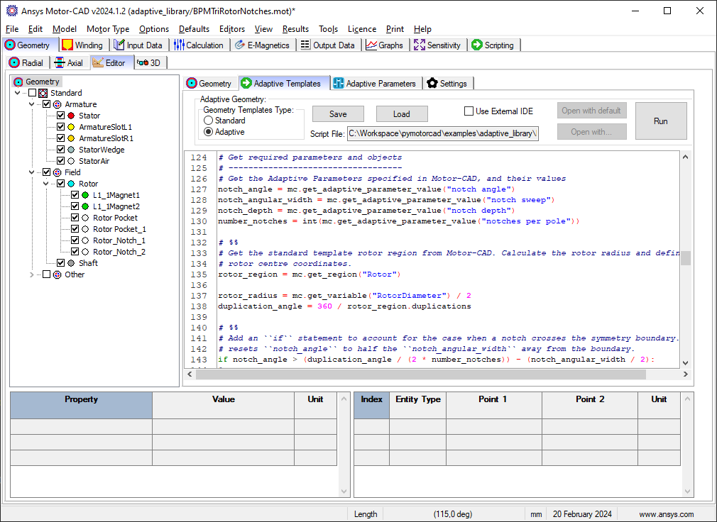
Geometry -> Editor -> Adaptive Templates tab in Ansys Motor-CAD 2024 R1#
To set an adaptive geometry for a Motor-CAD file, a script must be loaded in to the Adaptive Templates tab and run. Adaptive Templates Python scripts can also be executed externally, but unless the script is loaded in to the Adaptive Templates tab in Motor-CAD, the geometry is only defined temporarily.
Adaptive Templates Scripts require PyMotorCAD to be imported. This Python package provides access to Motor-CAD.
import ansys.motorcad.core as pymotorcad
ansys.motorcad.core provides access to the Motor-CAD geometry, such as the existing regions in
the model. It can be used to get an existing region from the Motor-CAD model (such as the Rotor)
as an object in Python (rotor = mc.get_region("Rotor")). It can also be used to set a Motor-CAD
region object in the Motor-CAD model (mc.set_region(rotor)).
For a Motor-CAD region object that has been obtained using PyMotorCAD, the region properties are accessible via Python. The region object created in Python contains all of the region properties shown in the Motor-CAD UI and all of the geometry entities that make up the region.
Properties such as the material and colour can be edited with an Adaptive Templates Script:
# Connect to Motor-CAD
mc = pymotorcad.MotorCAD()

# Get rotor region from Motor-CAD
rotor = mc.get_region("Rotor")

# Edit region properties
rotor.colour = (186, 85, 211)
rotor.material = "M470-50A"
mc.set_region(rotor)
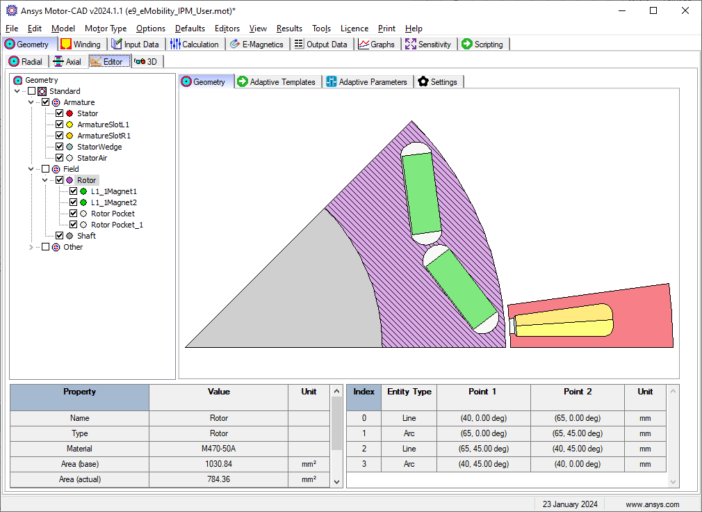
Rotor geometry with modified colour and material shown in the Geometry -> Editor -> Geometry tab#
Details on the Adaptive Geometry functions within ansys.motorcad.core that provide access to the
Motor-CAD geometry are available in the MotorCAD API under
Adaptive Geometry.
Using the geometry objects and functions library#
Adaptive scripts also require the ansys.motorcad.core.geometry library to modify the model
geometry. This provides geometry capability in Python, such as regions and entities. It is required
so that Lines and Arcs can be defined or modified by the script, and so that regions can be created
from these entities.
The geometry package can be imported:
import ansys.motorcad.core.geometry as geometry
Alternatively, specific functions (for example Line and Arc) can be imported from the package:
from ansys.motorcad.core.geometry import Line, Arc
ansys.motorcad.core.geometry is required to edit the entities that belong to a region, such as
changing the Lines or Arcs that define the region geometry.
Details on the full list of Geometry objects and functions are available in the API reference under Geometry objects and functions. For examples on modifying a Motor-CAD model geometry, see Adaptive templates examples.
Adaptive parameters#
An Adaptive Templates script can be set based on the Standard Template parameters or based on custom Adaptive Parameters. Adaptive Parameters are shown in the Geometry -> Editor -> Adaptive Parameters tab.
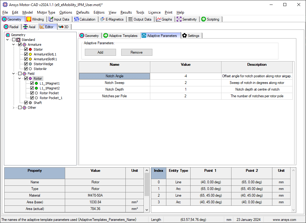
Geometry -> Editor -> Adaptive Parameters tab in Ansys Motor-CAD 2024 R1#
Any parameter can be defined, with a name, value, and description. Parameters can be added within
the Motor-CAD interface, or with a Python script. You can define an Adaptive Parameter, along with a
default parameter value, in the Adaptive Templates script. To do so, use the
set_adaptive_parameter_default() method from ansys.motorcad.core:
mc.set_adaptive_parameter_default("Notches per Pole", 2)
This checks whether the Adaptive Parameter already exists. If the parameter does not exist, it
creates the parameter and sets the value to the specified default value. If the parameter already
exists in Motor-CAD, the current value is kept and it is not set to the default value. To
set an Adaptive Parameter value, you can use the set_adaptive_parameter_value() method from
ansys.motorcad.core.
Adaptive Parameters also appear in the Geometry -> Radial tab, alongside the Standard Template parameters.
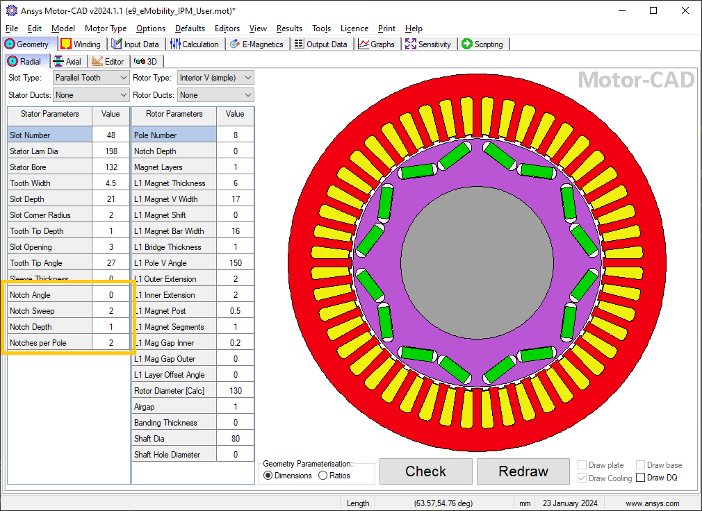
Adaptive Parameters shown in the Geometry -> Radial tab#
Adaptive Parameters can be accessed with the Adaptive Templates script using the
get_adaptive_parameter_value() method from ansys.motorcad.core, so that the geometry can be
defined by these Adaptive Parameters:
number_notches = int(mc.get_adaptive_parameter_value("Notches per Pole"))
Scripting workflow#
As well as the defined Adaptive Parameters, any parameter from Motor-CAD can be used in the Adaptive
Templates script by using the get_variable() method from PyMotorCAD. Any Motor-CAD API
accessible by PyMotorCAD is available.
For example, when modifying the rotor geometry, it is often useful to retrieve the rotor radius:
rotor_radius = mc.get_variable("RotorDiameter") / 2
Adding a region to the geometry#
To add a new geometry feature to the Motor-CAD model, such as a notch, the workflow is as follows:
A new region is created to represent the notch.
The region properties are defined (material, colour etc.).
Entities are added to the region to define the geometry (shape and position).
The parent region is defined for the new region (for a rotor duct example, the parent would be set to the rotor region).
The new region is set in Motor-CAD.
Creating a region#
To create a new region to represent the notch, use the Region object from
ansys.motorcad.core.geometry:
from ansys.motorcad.core.geometry import Region, RegionType

notch = Region(region_type=RegionType.rotor_air)
When creating new regions, it is recommended to set the
RegionType to the appropriate type of geometry component. For a full list of available region
types, see the RegionType entry under Geometry objects and functions.
Defining region properties and parent#
Region properties can be set using the appropriate field/property:
notch.name = "Rotor_Notch_1"
notch.colour = (255, 255, 255)
notch.material = "Air"
If the region object of the rotor has been created in Python (rotor = mc.get_region("Rotor")),
the rotor region object’s properties can be obtained and set for the rotor notch.
The Region.duplications property represents the symmetry of the region. In the example shown
using the e9 IPM template, duplications = 8 because there are 8 rotor poles of 45 °
symmetry. In this example, the notch would have the same symmetry as the rotor.
The parent region of the notch can be set to the rotor region so that the notch is set as a sub-region. Motor-CAD uses implicit subtractions so that the notch subtraction is handled automatically. The notch appears as a sub-region of the rotor in tree shown in the Geometry -> Editor tab in Motor-CAD.
notch.duplications = rotor_region.duplications
notch.parent = rotor_region
Adding entities to a region#
The geometry of a Region is made up of entities (Line and Arc objects). When entities are added to a Region, they must be added in anticlockwise order.
To add two Lines line_1, line_2 and an Arc airgap_arc to the notch region, use the
Region.add_entity() function from ansys.motorcad.core.geometry:
notch.add_entity(line_1)
notch.add_entity(line_2)
notch.add_entity(airgap_arc)
Line and Arc entities can be defined using Motor-CAD Coordinate objects. The Region.add_entity()
method adds an entity to the Region at the end of the entity list. Alternatively, the
Region.insert_entity() method inserts an entity at a specified index of the entity list,
allowing new entities to be inserted between two existing entities.
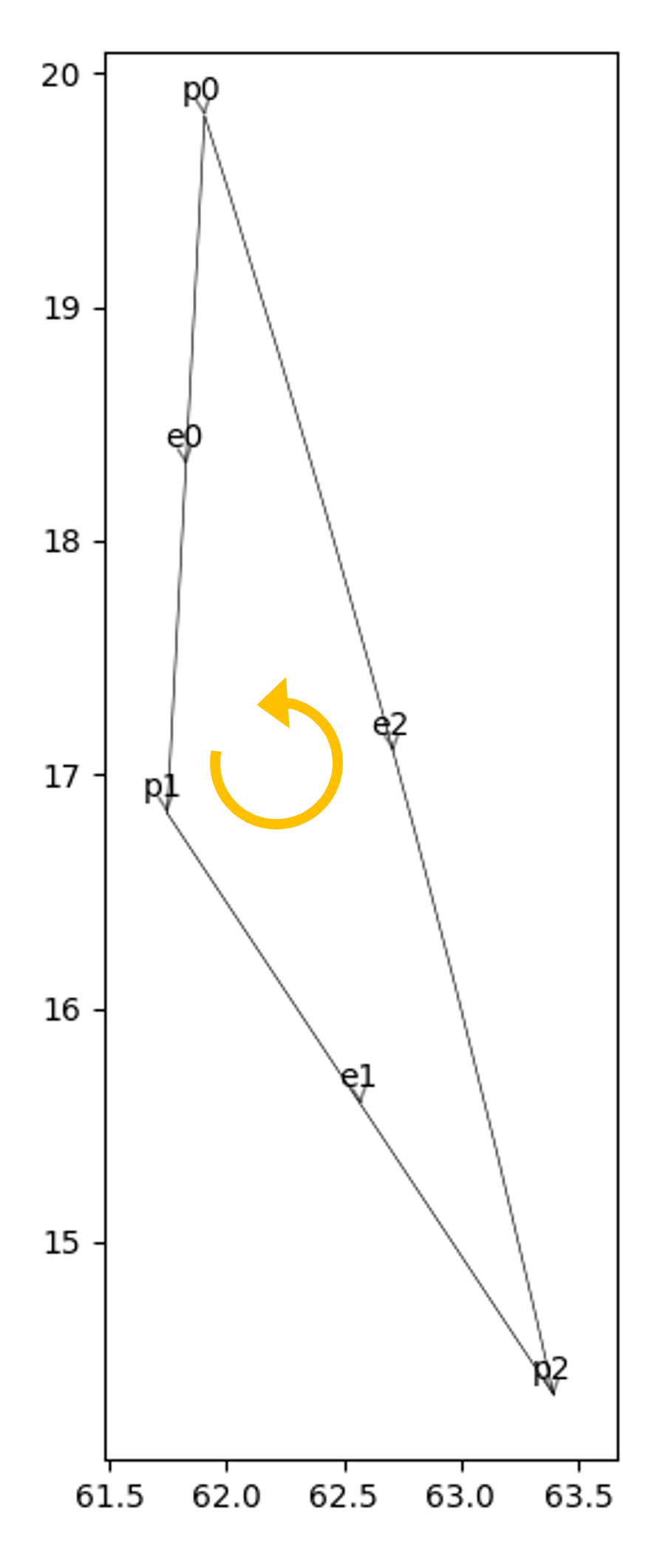
Three entities, e0 (line_1), e1 (line_2) and e2 (airgap_arc), making up
a triangular notch Region. The entities are in order going anti-clockwise around the Region.#
Because the entities have been correctly added in anti-clockwise order:
The end point
line_1.endis the start pointline_2.start(p1),the end point
line_2.endis the start pointairgap_arc.start(p2) andthe end point
airgap_arc.endis the start pointline_1.start(p0).
This means that the Region is closed and could be set in Motor-CAD.
Setting a region in Motor-CAD#
To set the notch in the Motor-CAD model, the notch region is sent to Motor-CAD using the
set_region() function from ansys.motorcad.core.
Region.is_closed() can be used to ensure that the entities that were added to the region create
a closed region.
if notch.is_closed():
    mc.set_region(notch)
Attempting to set a Region in Motor-CAD that is not closed, or where the entities are not in anti-clockwise order, may cause issues with the geometry and the FEA calculation may fail.
Using the geometry shapes library#
Line and Arc entities are defined using Motor-CAD Coordinate objects. Calculating the coordinate positions can be time-consuming and can require many lines of Python script.
For commonly used shapes, ready made functions can be used to create a region, based on a few
required parameters. These functions can be imported from the
ansys.motorcad.core.geometry_shapes library.
A function for creating a triangular notch region can be imported:
from ansys.motorcad.core.geometry_shapes import triangular_notch
The triangular_notch() function requires four arguments:
radius: Radial position of the notch outer edge. (For a rotor notch, this is the rotor radius.)sweep- Sweep of the notch along the rotor airgap, in degrees. (This parameter defines the notch width.)centre_angle- Angular position of the notch centre.depth- Depth of the notch
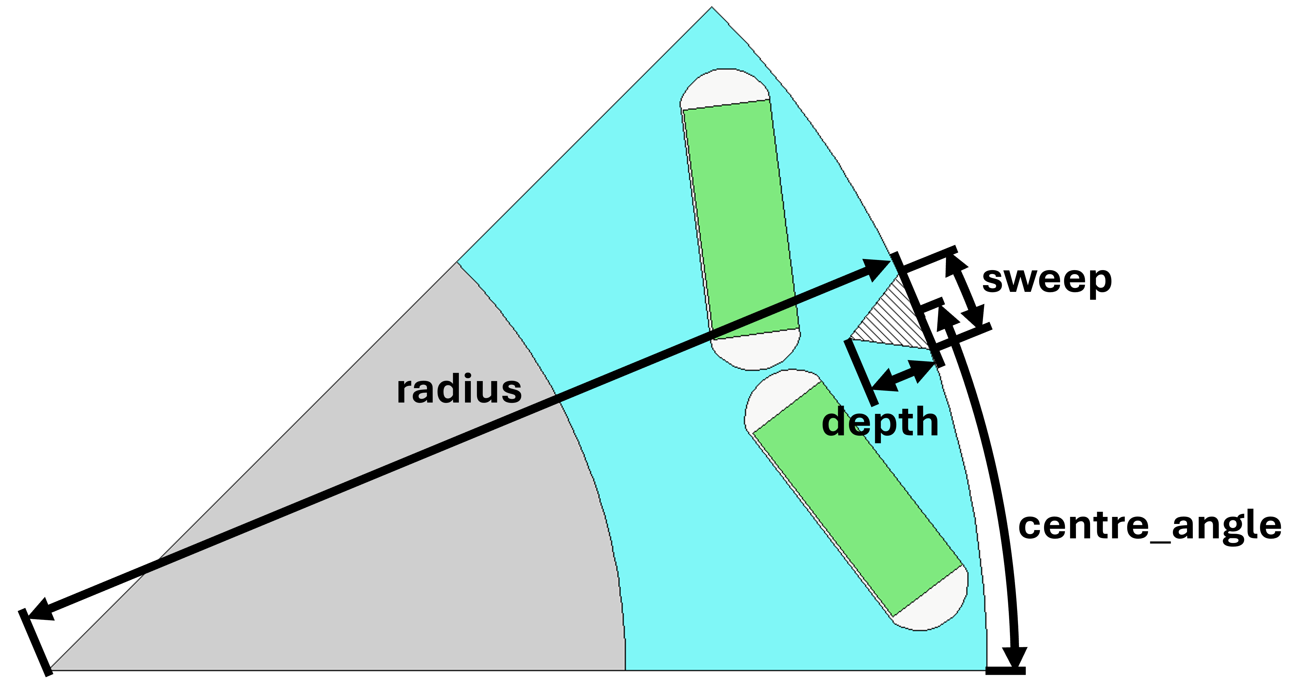
Required arguments for the triangular_notch() function.#
A rotor notch can be defined using this function so that the coordinates for the notch entities do not need to be calculated.
To use the triangular_notch() function to create a triangular rotor notch region:
notch = triangular_notch(
    rotor_radius, notch_angular_width, notch_centre_angle, notch_depth
)
The arguments, rotor_radius, notch_angular_width, notch_centre_angle and
notch_depth must be calculated in the Adaptive Templates script and specified.
The notch region properties can then be defined and the region can be set in Motor-CAD, as described earlier.
For a full Adaptive Templates example using the workflow described here, see Triangular Rotor Notches for IPM.
Details on the Geometry Shapes functions within ansys.motorcad.core.geometry_shapes are
available in the API reference under Geometry shapes.
Create and modify adaptive templates scripts#
Adaptive Template Scripts should be created outside Motor-CAD, using a Python Integrated Development Environment (IDE) (for example PyCharm or VSCode). Using an IDE allows for faster creation of the script, allowing access to autocompletion, code correction and other features which are not available in the Motor-CAD scripting interface.
This is essential when writing complex scripts, allowing issues with the script to be fixed and the inspection of Python objects, such as geometry regions from Motor-CAD.
Working on the adaptive templates script#
it is important to ensure that the Adaptive Template script contains this method before getting or setting any Motor-CAD geometry:
mc.reset_adaptive_geometry()
Adaptive Templates scripts can be edited from an external IDE (for example PyCharm or VSCode). To work on an Adaptive Templates script in an IDE, go to the Geometry -> Editor -> Adaptive Templates tab and select Adaptive under Geometry Templates Type. Save the script to a convenient location, and tick the Use External IDE option. The Adaptive Templates script is greyed-out and unavailable to edit within the Motor-CAD GUI when this option is selected.
To open the Adaptive Templates script file in your default IDE, click Open with default. To choose a specific IDE, click Open with.
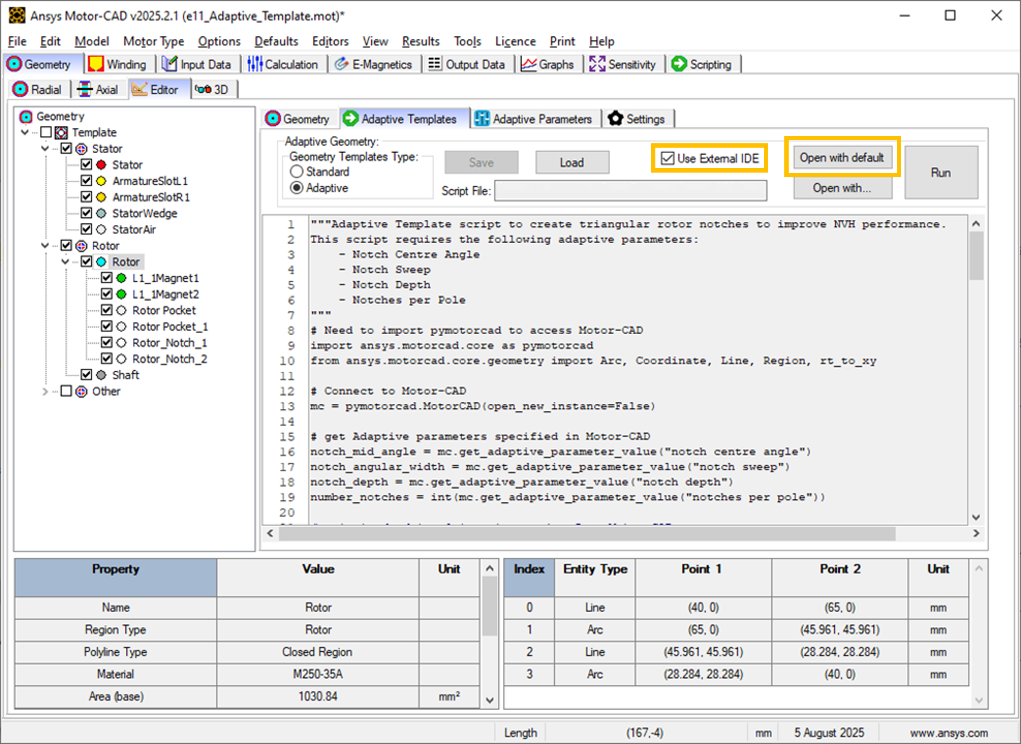
Use External IDE options in the Motor-CAD GUI.#
Adaptive Templates scripts should use the open_new_instance=False option when connecting to
Motor-CAD.
mc = pymotorcad.MotorCAD(open_new_instance=False)
Once the Adaptive Templates script is opened in the IDE, you can take advantage of functions such as
doc strings and debugging when working on the script. The Adaptive Templates script can be run within
the IDE, and the commands communicate with the open Motor-CAD instance when the
open_new_instance=False option is used.
For example, you can add a break point and run a script in debug mode to investigate the variables.
In the screenshot below, a break point has been added to pause the script before setting a new notch
region in Motor-CAD. Looking into the variables, you can find the notch region object and
investigate its attributes and properties. It has 3 entities (two Line objects and one Arc object).
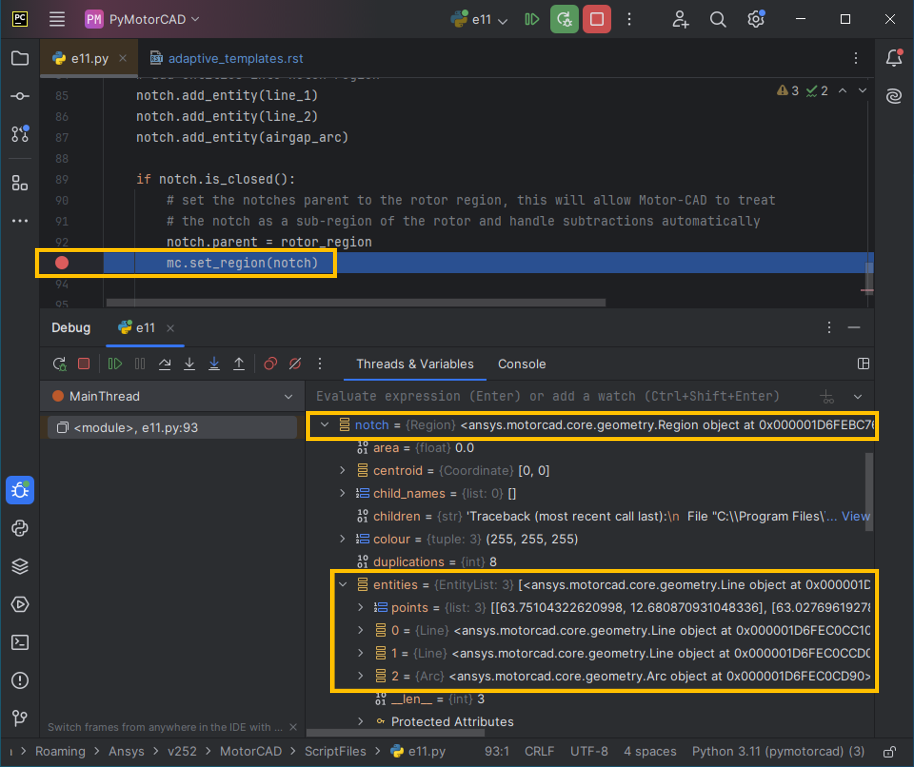
Using a break point in an Adaptive Template script to investigate variables.#
This is a useful tool when working on a Python script, such as an Adaptive Templates script. You can look into the properties of the Region object, as well as those of the entities such as the start, end and midpoint coordinates, the angles of Line objects, the radii of Arc objects.
IDEs (for example PyCharm or VSCode) have a lot of useful features for editing Python scripts. It is much easier and more efficient to use an IDE to develop Adaptive Templates scripts, rather than the editor within the Motor-CAD GUI. The Motor-CAD GUI is best suited for making small edits to a script.
Drawing geometry objects#
When working on and debugging Adaptive Templates scripts, it is useful to use the geometry drawing
feature to plot the geometry objects and regions. ansys.motorcad.core.geometry_drawing contains
the draw_objects() function, which can be used to plot any region that has been defined in
Python.
By default, this function only plots regions when called from an external IDE to assist with
debugging scripts. To plot regions from the Motor-CAD scripting interface, use the option
draw_objects(objects, draw_internal=True).
It can also be useful to draw the points and region labels, which can be enabled using the options
draw_objects(objects, label_regions=True, draw_points=True). For more information on the
different options available with the draw_objects() function, see Geometry drawing.
The geometry drawing package can be imported:
from ansys.motorcad.core.geometry_drawing import draw_objects
In the Curved Rotor Flux Barriers for SYNCREL U-Shape example, curved flux barrier (rotor pockets) region
objects are added to a list, pockets_all_layers. For more information on the Synchronous
Reluctance machine geometry with curved flux barriers used for this example, see
Curved Rotor Flux Barriers for SYNCREL U-Shape.
The draw_objects() function can be used to plot the regions:
draw_objects(pockets_all_layers, label_regions=True, draw_points=True)
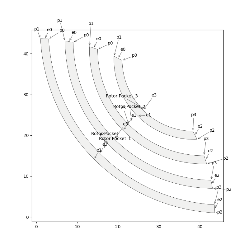
Plot of rotor pocket regions drawn using the draw_objects() function.#
Add imported DXF geometries to adaptive templates#
Custom geometry can be imported to Motor-CAD from a DXF file. For information on how to import custom geometry from a DXF file, see the “Custom Machine Geometries” tutorial supplied with Motor-CAD.
Once a custom geometry is imported, it is automatically separated into regions, which appear under
Import in the Geometry -> Editor tab. These imported geometry regions are accessed using
the get_region_dxf() method from the ansys.motorcad.core API. The geometry regions that are
currently set in the Motor-CAD model are shown under Template in the tree.
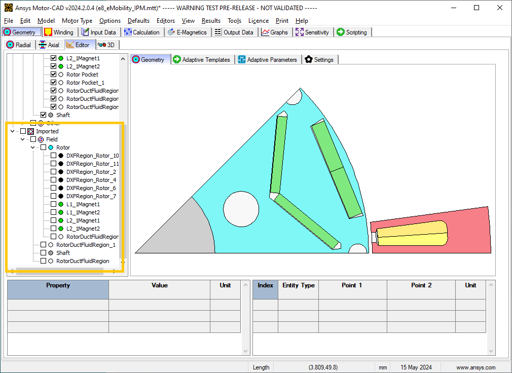
Geometry -> Editor -> Geometry tab with an imported custom geometry from DXF file.#
By default, the imported regions are not displayed. To display an imported region, select the checkbox.
Imported regions are not automatically set in the Motor-CAD model or used by the Motor-CAD calculations. To customise the Motor-CAD template geometry with the imported geometry, use Adaptive Templates.
Use the get_region_dxf() method in an adaptive templates script to access an imported region.
You can then modify and interact with the region in the same way as for any other region object.
The name, properties, and parent regions of the imported region can be defined.
To replace an existing region with an imported DXF region, use the Region.replace() method.
As with any region object, it is set in the Motor-CAD model using the set_region() method. The
imported region then appears under Template in the Geometry tree shown in the
Geometry -> Editor -> Geometry tab in Motor-CAD.
Best practices for Adaptive Templates scripting#
Adaptive Templates scripts in Motor-CAD can be used in many different ways to customise the electric machine geometry. Some approaches are more challenging than others. For some types of geometry customisation, there are some recommended approaches and best practices that should be followed.
Modifying stator slot openings#
When using Adaptive Templates to modify the shape of the stator slot opening, there are some best practices which may be followed to make the process simpler.
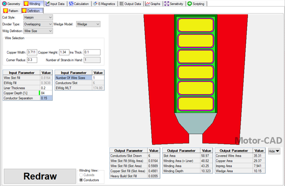
If the modifications reduce the available space for conductors, then the Copper Depth [%] parameter in the Winding -> Definition tab should be adjusted to reflect the available space for conductors in the updated slot.
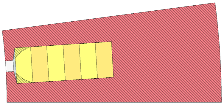
A Motor-CAD stator geometry where the stator slot has been modified to be narrower at the slot opening. The Stator region (red, shaded) intersects the ArmatureSlot regions (yellow) and the Wedge region (grey). The Copper Depth [%] is still set to 100 %, so the ArmatureSlot regions are still being drawn based on the unmodified Standard Template geometry.#
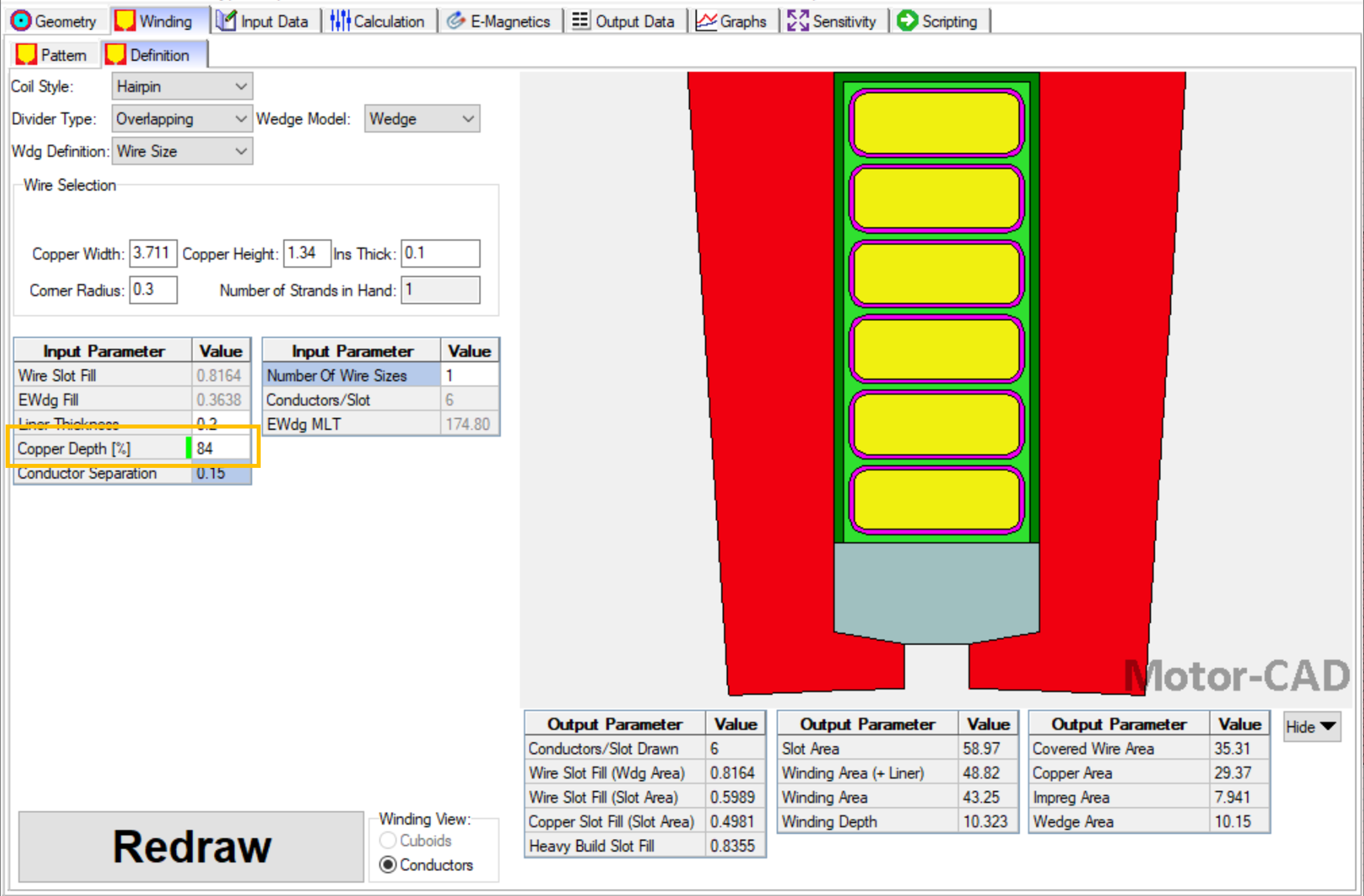
The Winding -> Definition tab in Motor-CAD. Setting the Copper Depth [%] to 84 % means that the conductors, impregnation and slot liner now only fill 84 % of the slot. This reflects the amount of space available in the modified slot.#
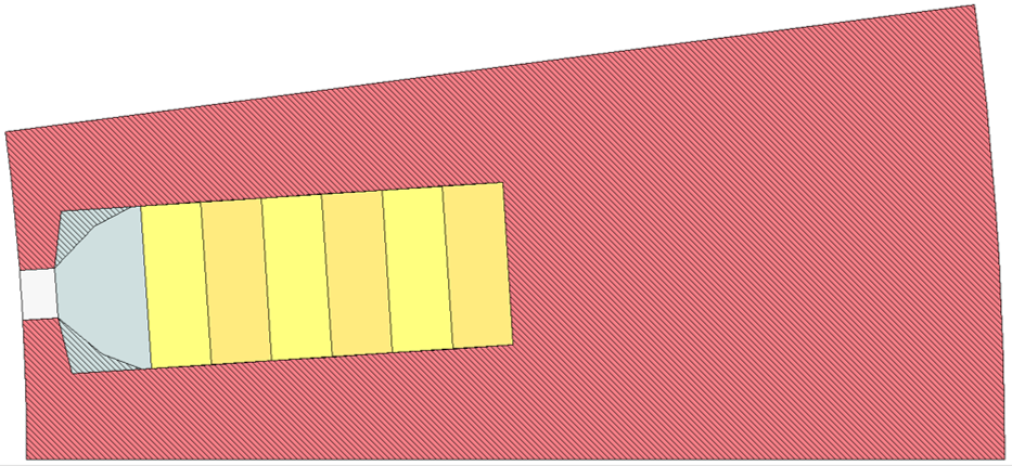
With the updated Copper Depth [%], the Stator region (red, shaded) no longer intersects the ArmatureSlot regions, only the Wedge region (grey).#
To modify the shape of the Wedge region based on a modified Stator slot geometry, subtract the Stator region from the Wedge:
wedge = mc.get_region("Wedge")
wedge.subtract(modified_stator)
mc.set_region(wedge)
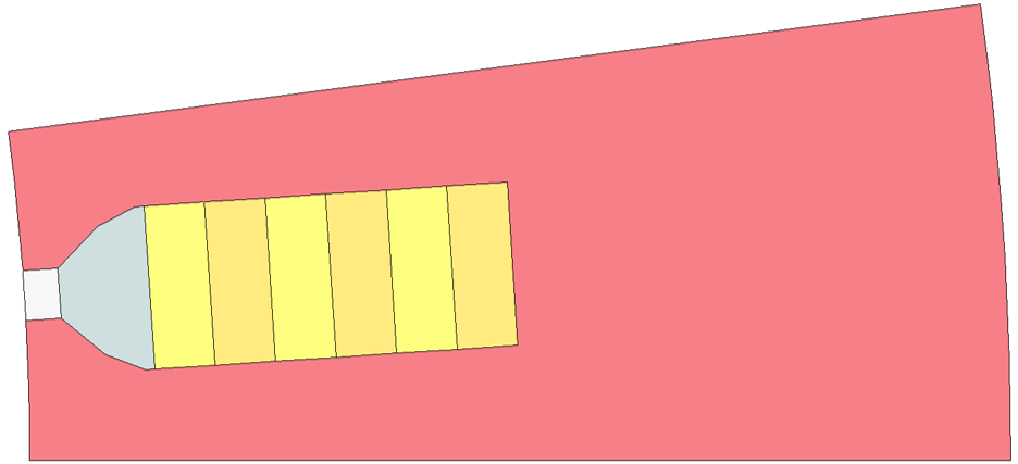
When the Wedge region has been modified by subtracting the modified Stator region, the custom stator slot geometry is complete.#
The updated stator slot can also be visualised in the Winding -> Definition tab, now that the wedge has been updated.#
Rounding corners of geometry regions with Adaptive Templates#
The Motor-CAD Standard Template geometry has options for automatic corner rounding of the rotor lamination and magnets (found on the Input Data -> Settings -> Geometry tab). When corner rounding is enabled, the sharp corners of regions are modified, inserting Arc entities at the corners.
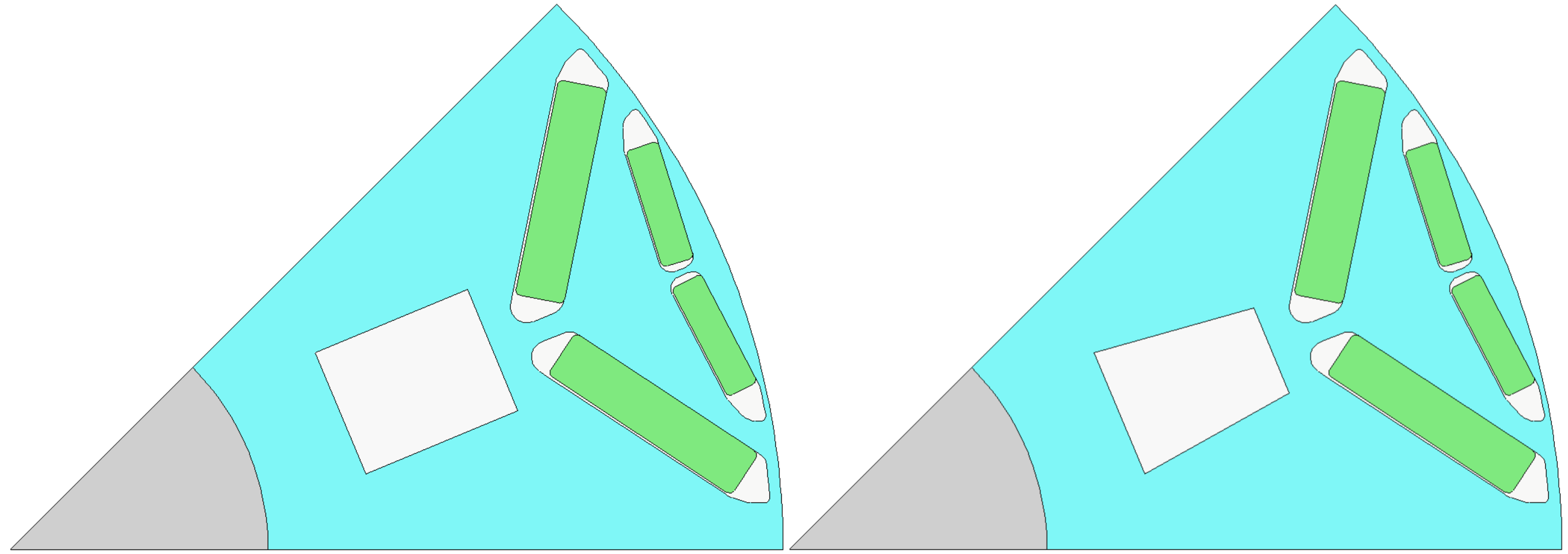
The e10 IPM template rotor geometry in Motor-CAD without (left) and with (right) corner rounding enabled for the rotor lamination and magnets.#
Looking closely at an the e10 IPM Motor-CAD template example, when corner rounding is not enabled, the Rotor Pocket regions have an inner corner formed by two Line entities (entity 3 and 4).
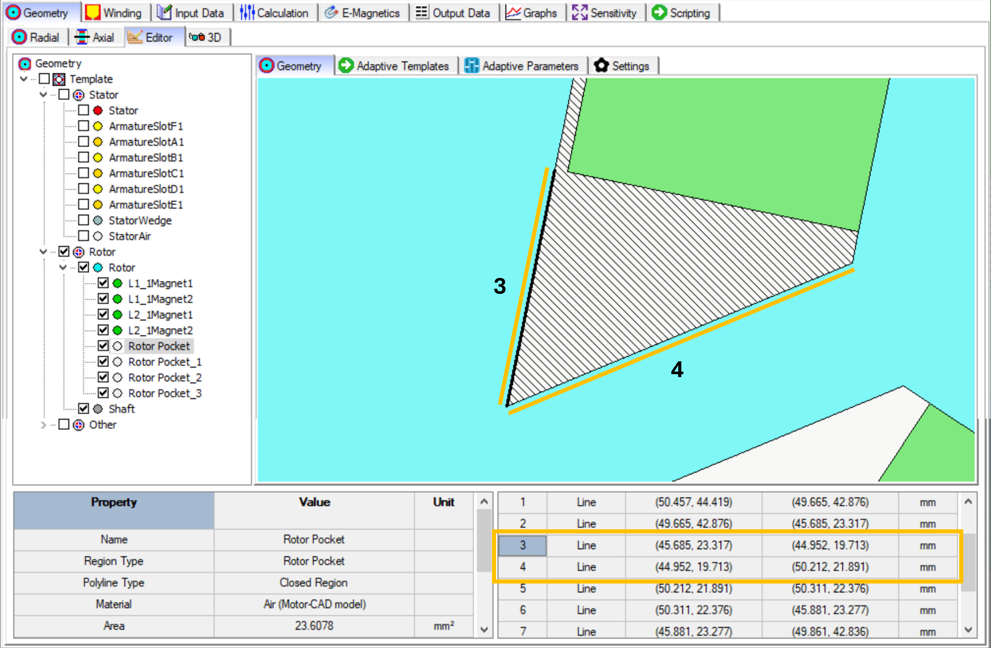
A corner made up of two Line entities (entity 3 and 4).#
When corner rounding is enabled, the Rotor Pocket region is made up of a larger number of entities. The same corner is now formed from two Line entities (entity 7 and 9) with an Arc between them (entity 8). The lines have been shortened and an Arc has been inserted between them at the corner.
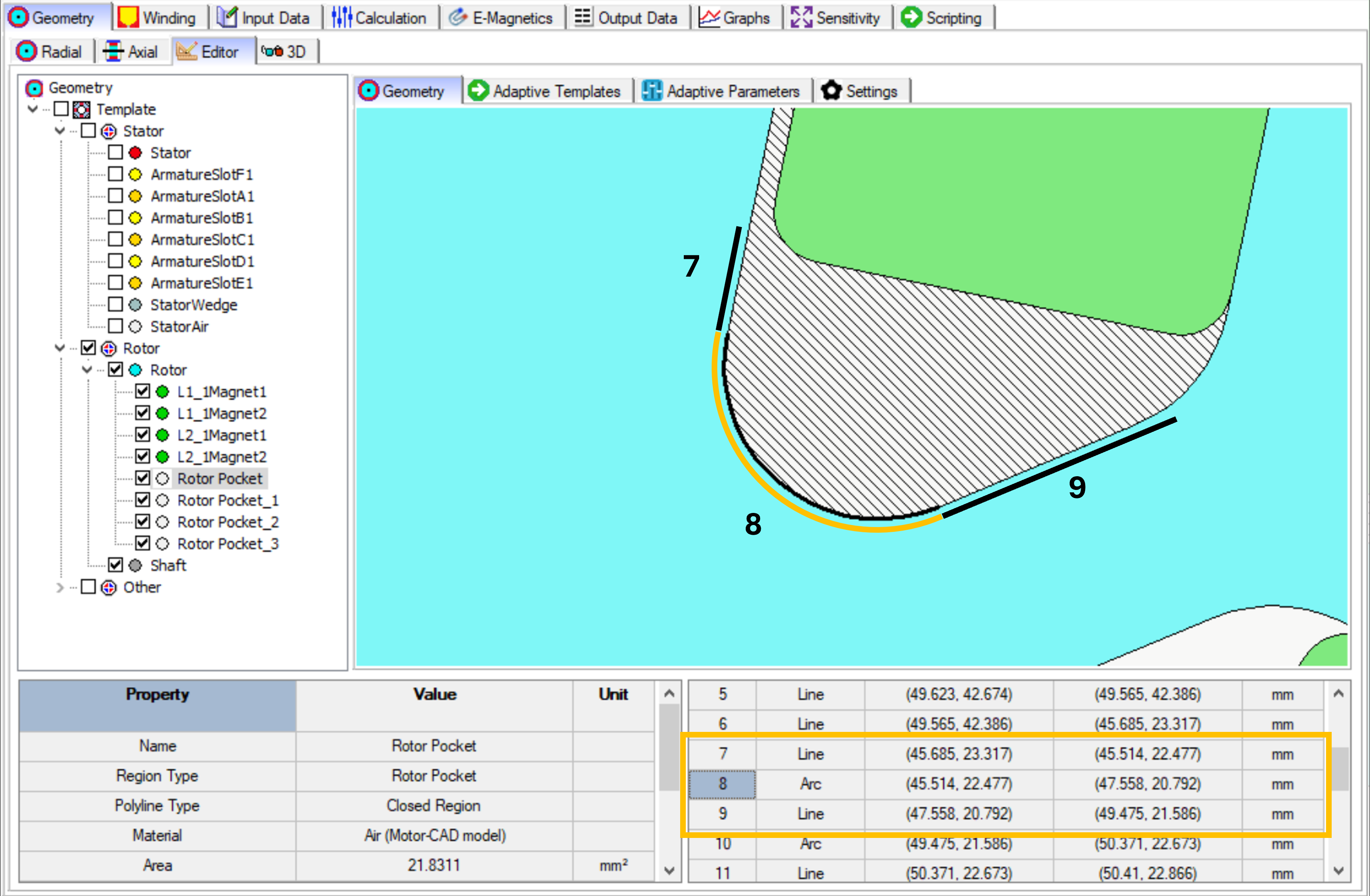
A corner made up of two Line entities (entity 7 and 9) and an Arc (entity 8).#
When customising a Motor-CAD geometry with Adaptive Templates, it is much simpler to modify the geometry when corner rounding is not selected. This is because there will be fewer entities forming the regions (such as the rotor pocket and magnet regions). It is recommended to set the Corner Rounding (Rotor Lamination) and Corner Rounding (Magnets) parameters on the Input Data -> Settings -> Geometry tab to None (default).
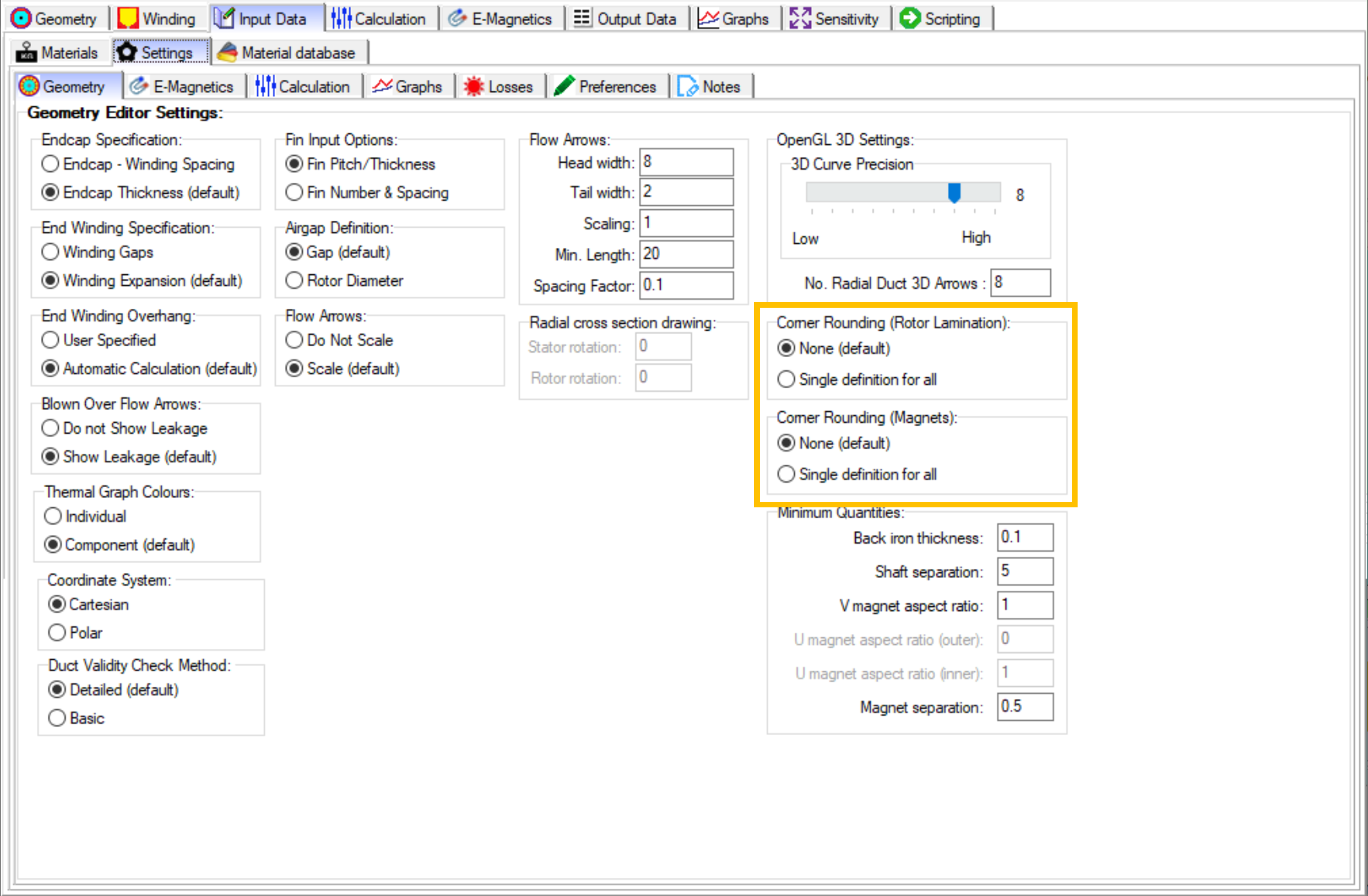
The Input Data -> Settings -> Geometry tab in Motor-CAD, showing the corner rounding options for the Standard Template geometry.#
The recommended best practice when using Adaptive Templates, is to first create the custom geometry
with ‘sharp’ corners, and subsequently round the corners. The Region.round_corner() and
Region.round_corners() methods can be used for automatically shortening the adjacent entities of
a corner, and inserting an Arc.
Considering the Trapezoidal ducts example, where a Standard Template geometry is set up with rectangular rotor ducts and the ducts are modified with Adaptive Templates to form trapezoid shapes. Rectangular ducts in Motor-CAD have a corner radius parameter (separate from the Corner Rounding (Rotor Lamination) parameter discussed earlier), which should be set to 0 mm when the rectangular duct is to be modified with Adaptive Templates. In this example, the ducts are modified by shortening the top line of the rectangular duct according to an Adaptive Parameter value. For the full example, see Trapezoidal ducts.
Standard Template geometry with a rectangular rotor duct (left) and Adaptive Templates geometry where the duct has been modified into a trapezoid shape (right).#
Once the ducts have been modified to form trapezoid shapes, the corners can be rounded using the
Region.round_corners() method before the updated Region is set in Motor-CAD. This method
requires two arguments:
The corner coordinates that are to be rounded
A corner radius to be applied to all corners
To get a list of all the region points, you can use duct_region.points.
# edit the rectangular duct to form trapezoid duct:
duct_region.edit_point(entity.start, new_start_point)
duct_region.edit_point(entity.end, new_end_point)

# draw the trapezoidal duct region before rounding the corners
draw_objects(duct_region, label_regions=True, draw_points=True)

# round the trapezoidal duct corners
duct_region.round_corners(duct_region.points, 1.5)

# draw the rounded trapezoidal duct region
draw_objects(duct_region, label_regions=True, draw_points=True)

# set the modified duct region in Motor-CAD
mc.set_region(duct_region)
For each of the corner coordinates, the Region.round_corners() method shortens the entities that
are adjacent to the corners and inserts Arc entities with the specified corner radius (1.5 mm).
The result is a modified Region with rounded corners.
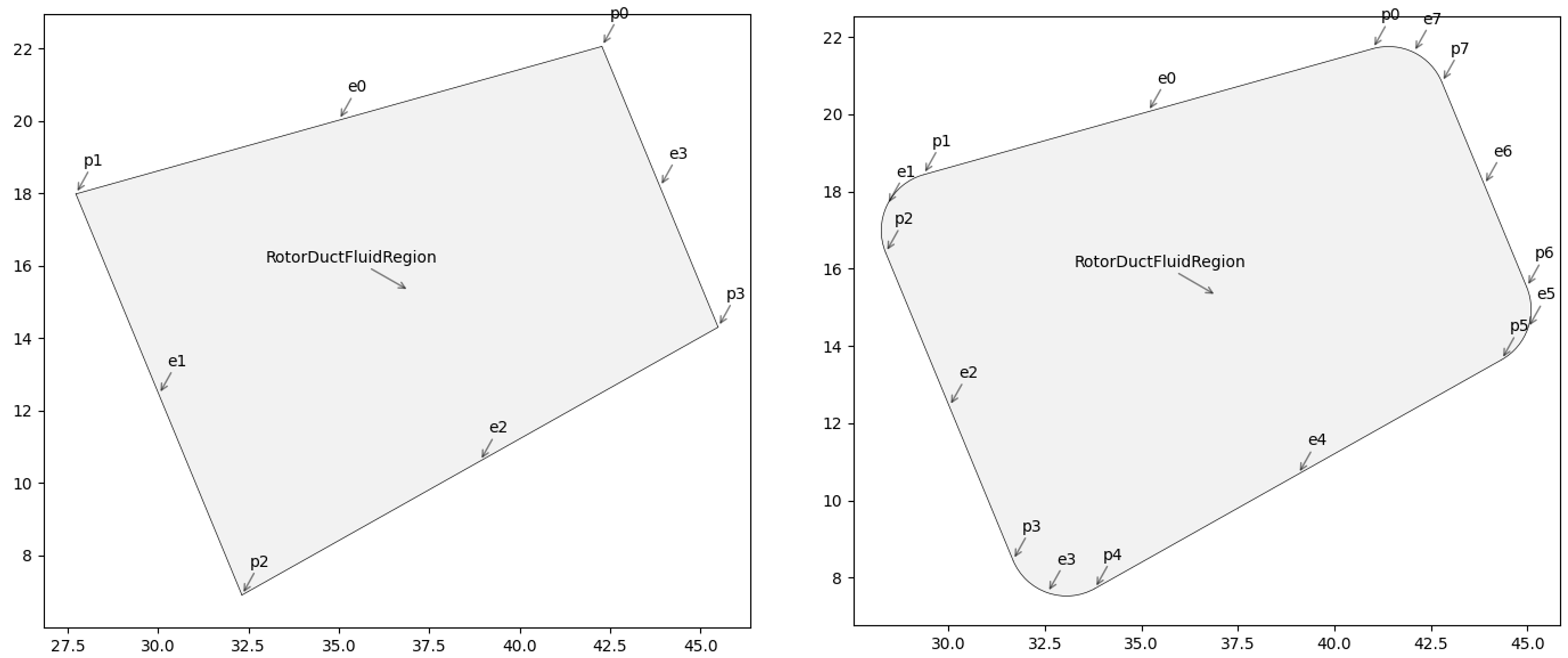
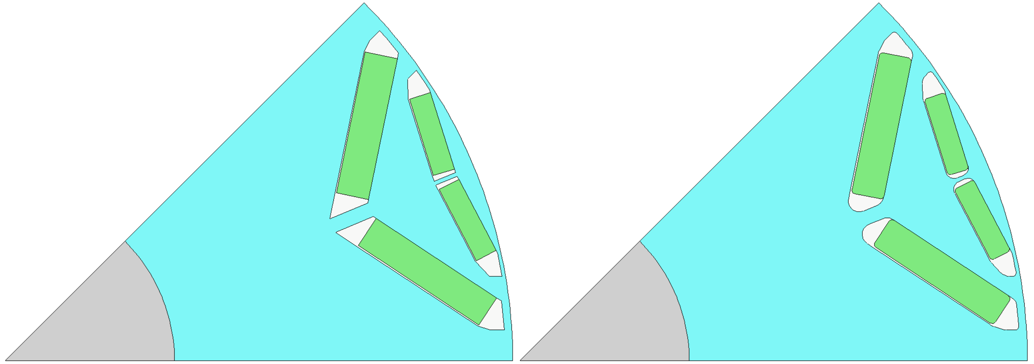
Figures plotted using the draw_objects() function of a trapezoidal rotor duct without (left)
and with (right) corners rounded by a radius of 1.5 mm.#
The updated rotor geometry with trapezoidal rotor duct in Motor-CAD.#
To apply different corner radii for each corner, you can use the Region.round_corner() method
and round corners individually.